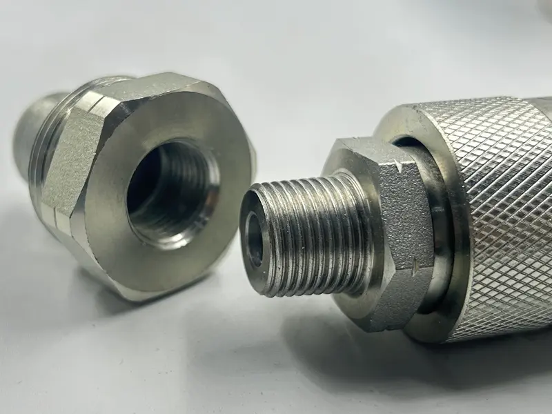
The “tread” on hydraulic quick couplings refers to the threads used to connect the coupling body to the hydraulic hose or other components. These threads are crucial for creating a secure and leak-free connection.
Understanding Hydraulic Threads: A Beginner’s Guide
Hydraulic couplings and fittings come in various thread types, making it essential to identify them correctly to ensure compatibility and prevent leaks. This guide will help you understand different thread standards, how to measure them, and common misconceptions.
Common Thread Standards in Hydraulics
There are several thread standards used in hydraulic applications. Below are the most common ones:
1. NPT (National Pipe Thread)
- Commonly used in North America.
- Tapered threads that seal by wedging together.
- Requires thread sealant or Teflon tape for a proper seal.

2. BSPP & BSPT (British Standard Pipe Parallel/Tapered)
- BSPP (Parallel) uses an O-ring or bonded seal for sealing.
- BSPT (Tapered) seals similarly to NPT but has different thread angles.
- Commonly used in Europe and Asia.
📌 Image Suggestion: Diagram comparing BSPP and BSPT threads. 📌 Image Description: Illustration showing the difference between BSPP parallel threads and BSPT tapered threads.
3. Metric Threads
- Common in European equipment.
- Available in fine and coarse pitch variations.
- Typically use an O-ring for sealing.
📌 Image Suggestion: Metric thread fitting comparison with caliper measurement. 📌 Image Description: Measuring a metric thread fitting to determine pitch and diameter.
4. JIC (Joint Industry Council)
- Uses a 37° flare fitting for sealing.
- Common in high-pressure hydraulic systems.
- Compatible with AN (Army-Navy) fittings.
📌 Image Suggestion: JIC fitting with a 37-degree flare detail. 📌 Image Description: Close-up of a JIC fitting showing the 37° flare angle used for sealing.
5. ORFS (O-Ring Face Seal)
- Uses an O-ring in the fitting’s face for a secure seal.
- Provides excellent leak prevention.
- Popular in high-pressure applications.
📌 Image Suggestion: ORFS fitting diagram showing sealing mechanism. 📌 Image Description: ORFS hydraulic fitting with a highlighted O-ring for sealing.
How to Measure Hydraulic Threads
Step 1: Determine If the Thread Is Parallel or Tapered
- Tapered threads get narrower as they extend.
- Parallel threads maintain a consistent diameter.
Step 2: Measure the Thread Diameter
- Use calipers to measure the outer diameter (OD) of male threads or inner diameter (ID) of female threads.
Step 3: Identify the Thread Pitch
- Use a thread pitch gauge to determine the number of threads per inch (TPI) or thread spacing in millimeters.
📌 Image Suggestion: Step-by-step process of measuring hydraulic threads. 📌 Image Description: Visual guide showing how to measure thread OD, ID, and pitch with calipers and a thread gauge.
Common Misconceptions About Thread Sizing
- Pipe thread sizes do not match actual measurements – For example, a 1/4” NPT thread does not have a 1/4” diameter.
- Different thread types are not interchangeable – Mixing thread types can cause leaks and fitting damage.
- Some threads require sealants, others don’t – NPT and BSPT require sealant, while ORFS and JIC rely on mechanical sealing.
Conclusion
Properly identifying hydraulic threads is crucial for system performance and leak prevention. By understanding thread types and how to measure them, you can ensure compatibility and avoid costly mistakes.
📌 Final Image Suggestion: Comparison chart of different hydraulic thread types. 📌 Image Description: Side-by-side comparison of NPT, BSPP, BSPT, Metric, JIC, and ORFS threads with key differences highlighted.

Leave a Reply